If you’ve been following the N997CZ build journal, you know the first five flights have been a mix of exhilarating milestones and humbling detective work. Flight 1 was a dream. Flight 2 sent me home early with erratic oil temperature gauges. Flight 3 gave me two solid hours and flaps for the first time. Flight 4 found an alternator belt slipping. But threaded through all of them was something I kept noticing and not fully understanding: in every single flight, the PFD #1 artificial horizon has tumbled upside down at least once.
That’s not a nuisance — that’s a serious ADAHRS event. Once I started pulling the deviation data from all five flights and laying them side by side, the pattern became impossible to ignore. I posted the data to the Van’s Air Force build thread and the community response was immediate, deep, and directly useful. This post is about what the data shows, what the community has experienced, what Garmin tech support confirmed, and my current working theory: this is primarily a vibration problem — with CAN bus wiring issues thrown in as a secondary layer.
What Does “ADAHRS % Deviation” Actually Mean?
N997CZ actually carries three ADAHRS units, all integrated into the G3X system. The G3X Pilot’s Guide confirms that the G3X supports up to three ADAHRS sources, with the G5 functioning as a full participant in the cross-comparison and miscompare monitoring via CAN bus — not a standalone backup, but a third integrated ADAHRS. The G3X uses two GSU 25C units — ADAHRS #1 and ADAHRS #2 — plus the Garmin G5, all cross-checked against each other. Both GSU 25Cs are mounted on the sub-panel directly forward of PFD #1. The G5 sits in a separate location, which makes its deviation data a valuable third data point — if its profile looks different from the GSU 25s, it helps localize where the disturbance is worst. That data is being pulled and will be added in a follow-up.
Before diving into the charts, an honest caveat: Garmin has not publicly disclosed what % deviation actually measures internally. We asked. They didn’t specify. So everything below is interpreted with that uncertainty in mind. It could be a cross-check residual between the two GSU 25 units, or something internal to each unit — perhaps related to Kalman filter covariance, or how much raw IMU data agrees with the filter’s predicted state. Without Garmin’s definition, we can’t be certain.
Working assumption: % deviation is a proxy for disturbance severity — higher is worse, sustained high values indicate a real problem. Garmin tech support declined to specify what maximum acceptable values should be. The 999% hard pegs have not been confirmed as caused by CAN bus dropouts specifically. Garmin’s guidance: fix the CAN bus first, then re-evaluate what remains.
Hypothesis on the 999% spikes: These hard pegs likely occur during takeoff as RPM sweeps upward from idle. The rising forcing frequency sweeps through the natural resonant frequency of the ADAHRS mount — where vibration transmission into the sensor peaks. Once RPM stabilizes at cruise, the deviation drops to an elevated-but-lower baseline. This is consistent with classic mass-spring-damper resonance behavior and with community reports of problems being RPM- and power-setting-dependent.
Several things can drive this, in rough order of likelihood for a new RV-10: an unbalanced or un-clocked prop; GSU 25 mount resonance amplifying vibration at one sensor location; loose lower cowl hinge pins transmitting vibration into the firewall; and CAN bus dropouts causing the cross-check math to fail and peg at 999%.
Five Flights of Data
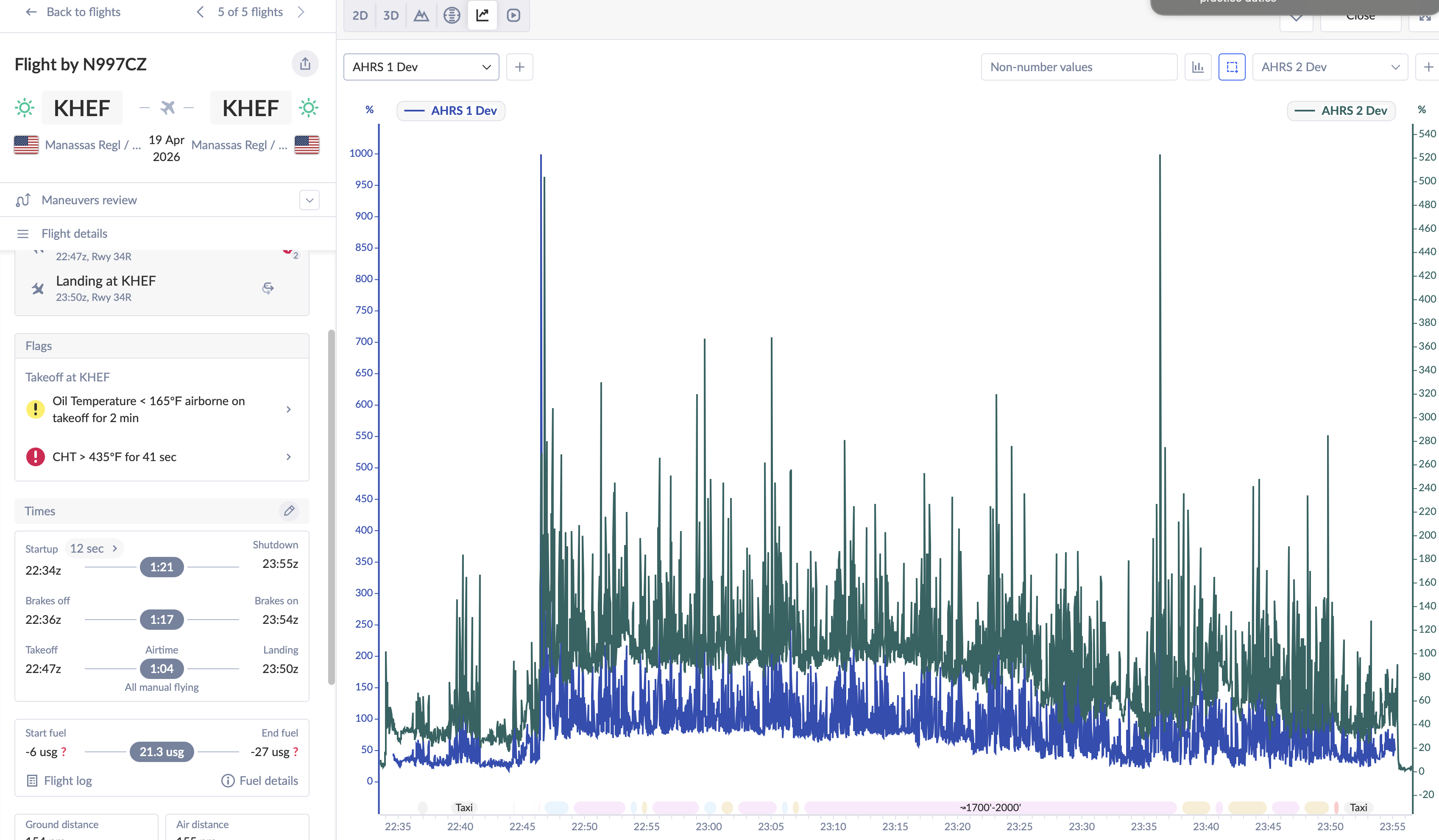
Blue = ADAHRS #1 | Teal/green = ADAHRS #2. A flat, quiet trace near zero is healthy. What you’ll see instead is large % deviation in both sensors from takeoff to touchdown across all five flights — sustained throughout every flight, not isolated spikes.
Flight 1 — April 11, 2026 (First Flight, 127 nm)
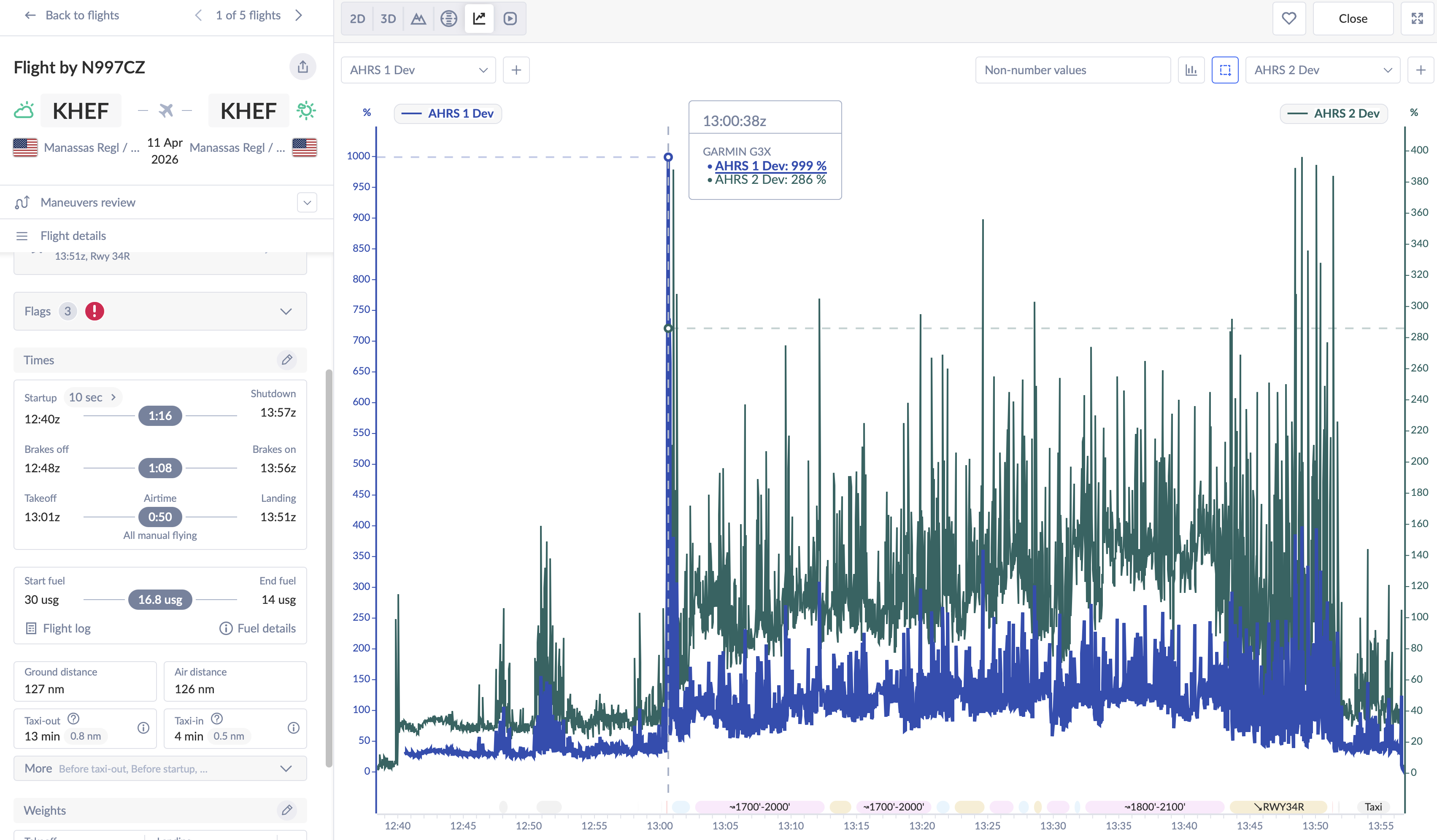
The very first flight and already there’s a clear problem. Both sensors show elevated deviation from shortly after takeoff through landing. ADAHRS #2 is consistently worse than #1, with a hard 999% peak around 13:00:38. The sustained asymmetry between the two units throughout the flight points to a physical difference in what each sensor location is experiencing. The horizon tumbled on this flight — PFD #1 only.
Flight 2 — April 17, 2026 (Abbreviated, 68 nm)
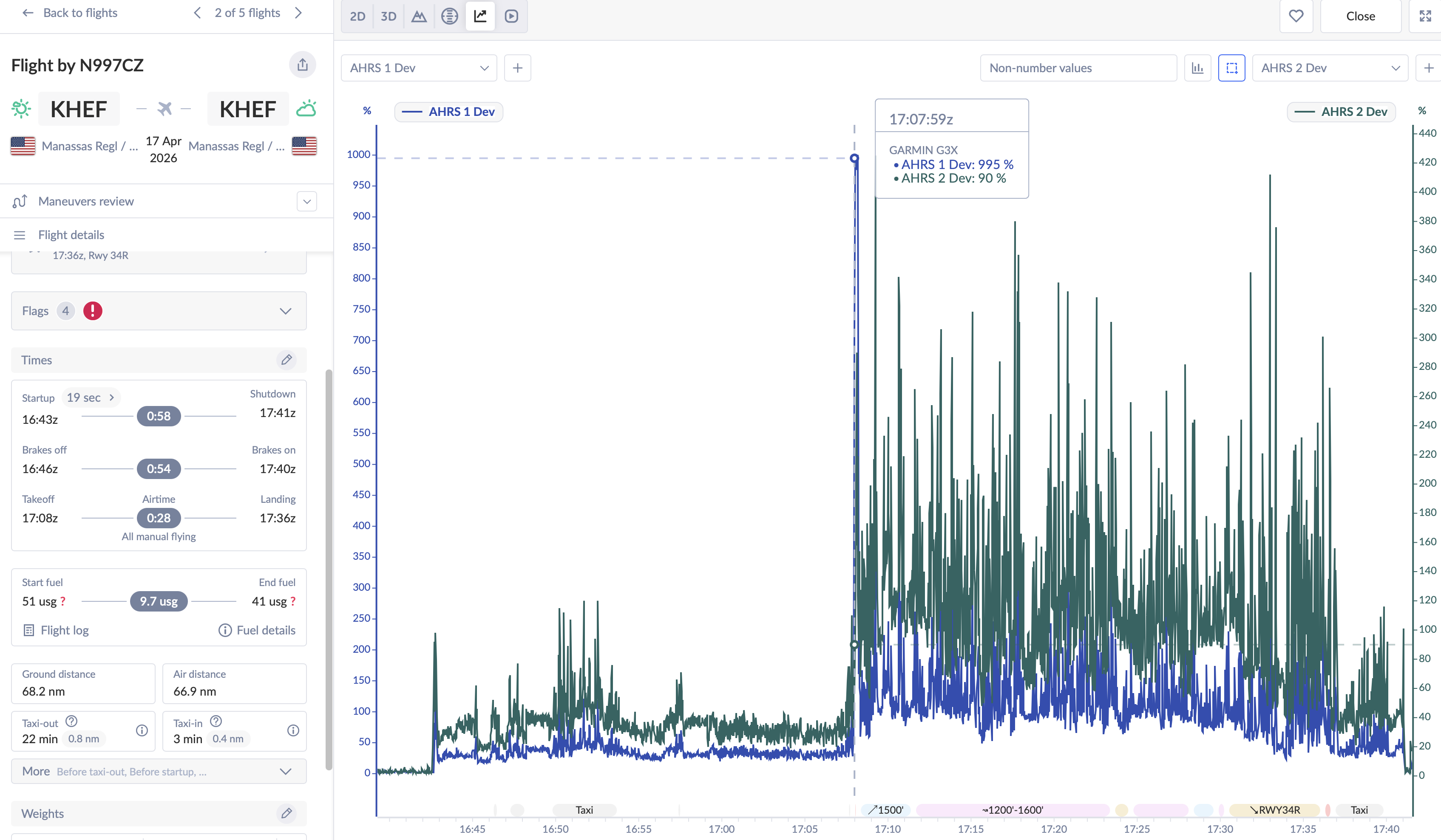
Identical story to Flight 1. Large deviation in both sensors from takeoff to landing, #2 running consistently worse than #1. The repeatability across two flights makes it clear: this is not random noise. The horizon tumbled again.
Flight 3 — April 18, 2026 (Two Hours West, Flaps First Time)
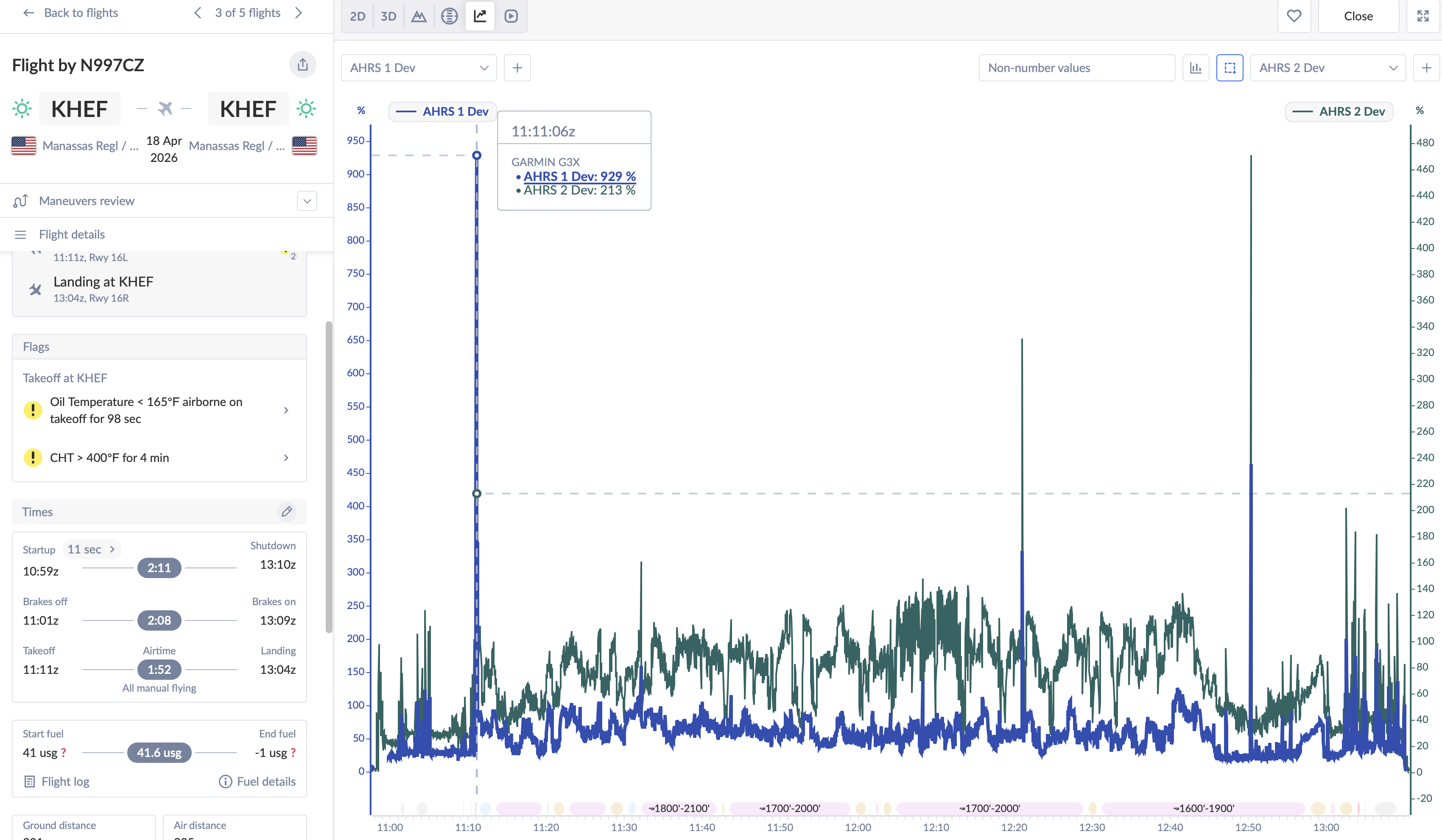
The two-hour flight shows the same sustained high deviation. What’s notable is a concurrent peak where both sensors reach similar values (229% and 233%) at the same moment — suggesting the disturbance is either broad enough to affect both locations equally, or the CAN bus dropouts confirmed by Garmin are contributing.
Flight 4 — April 18, 2026 (Alternator Belt Discovery)
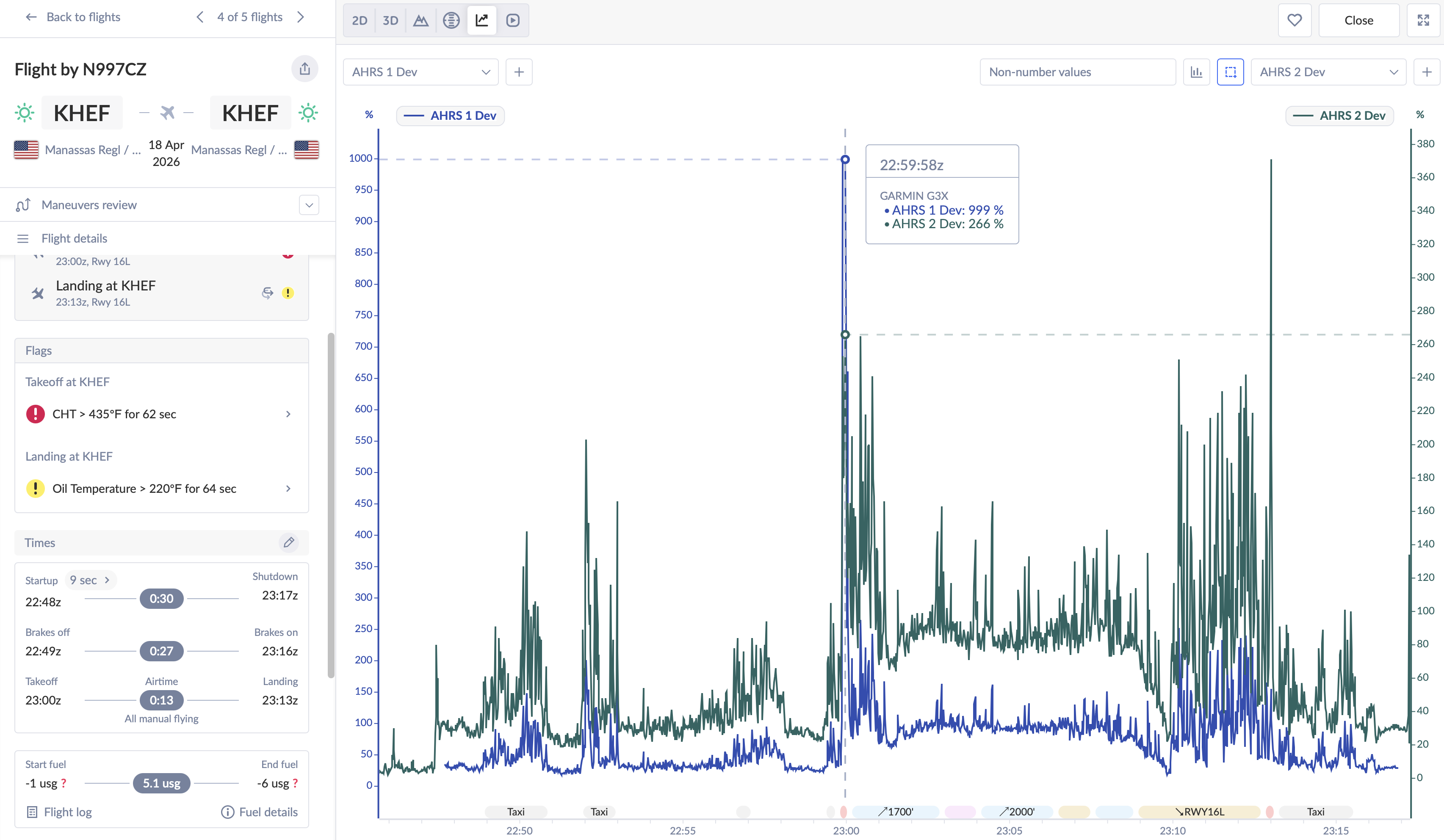
Large deviation in both sensors across the whole flight, #2 running consistently worse again. Flight 4 was when we discovered the alternator belt was slipping, though the ADAHRS deviation pattern is consistent with every other flight.
Flight 5 — April 19, 2026
Both sensors show large sustained deviation from takeoff to landing, same as every prior flight. The consistent, high deviation across all five flights is itself the story: this is not a problem that comes and goes — it is present in every flight, start to finish.
Coming next — G5 data: The Garmin G5 is mounted in the main instrument panel, further aft than the two GSU 25Cs on the sub-panel. The sub-panel is tied directly to the firewall via a fore/aft rib, making it a near-direct receiver of engine vibration. The main panel is at the end of a longer structural path with more joints and compliance. If the G5’s deviation runs lower than the GSU 25s — which early recollection suggests — that would directly implicate the sub-panel’s structural coupling to the firewall. That data is being extracted and will be added in a follow-up.
What the Van’s Air Force Community Has Experienced
I posted the data to the N997CZ build thread on VAF and the response was both immediate and sobering: this is a well-known problem, and multiple experienced builders have been down this exact road.
The GSU 25 Mount Location Is the Central Issue
Both GSU 25s are mounted on the sub-panel in the upper-left corner — close to the display, accessible, tidy. But multiple builders reported this location is problematic on the RV-10, and several noted a frustrating catch: Garmin’s ground-based vibration test passes in essentially every position. The only meaningful test is in flight at full power.
The community consensus is that stiffening the sub-panel — adding 0.063 angle stock, doublers, or bracing — doesn’t reliably solve the problem. Making the bracket stiffer just makes it a better conductor of vibration rather than isolating it. Multiple builders who resolved the problem did so by relocating the GSU units entirely: some to the back of the GDU display (despite Garmin’s manual discouraging this), others to a remote aft mount.
The community’s blunt summary: ground vibration tests are a waste of time for diagnosing this. You can’t simulate full power and flight conditions on the ground, and the GSUs will pass the test in any position — then fail in flight. The only data that matters comes from the air.
The Cowling Hinge Pin Fix (An Unexpected One)
One builder shared a fix I wouldn’t have thought to look for: the standard Van’s lower cowl piano hinge vertical pins. Their ADAHRS problem persisted through a sub-panel stiffener and a GSU hardware swap under the Garmin service bulletin. The breakthrough came when someone noticed the lower cowl vertical pins allowed a tiny amount of flex — detectable by hand-pressing the sides of the cowl against the firewall. Replacing those pins with slightly oversized ones resolved the AHRS drift over 30+ hours of subsequent flying.
The diagnostic tell was clean: the ADAHRS ground test passed with the cowl off and failed with the cowl on. N997CZ already uses heavier-than-standard pins, but I’ll be checking the lower vertical pins specifically — it’s a low-cost check worth doing early.
Garmin Service Bulletin SB 2144 — Both My Units Are Affected
Garmin issued SB 2144 specifically addressing GSU 25 units susceptible to “acoustic noise energy” — their language for vibration-induced sensor degradation. The bulletin was traced back to COVID-era supply chain issues that resulted in different MEMS components being used in a production run of units. Both of my GSU 25Cs fall within the affected serial number range.
Some builders had both units replaced under SB 2144 and reported clean results. However, others found the hardware upgrade alone wasn’t sufficient — it took the cowl pin fix or a mount relocation on top of the new units. The SB appears to be a necessary step, but not necessarily sufficient on its own.
Van’s Service Bulletin SB-00028 — Rubber Isolators
Van’s issued SB-00028 (currently RV-12 specific) directing owners to assess ADAHRS performance and, where issues are found, install rubber isolators on the GSU mounts. This directly contradicts Garmin’s guidance to mount to “the stiffest part of the airframe.” The community notes the irony, and the flight experience of multiple builders suggests Van’s got it right.
The Stiff vs. Soft Mount Debate
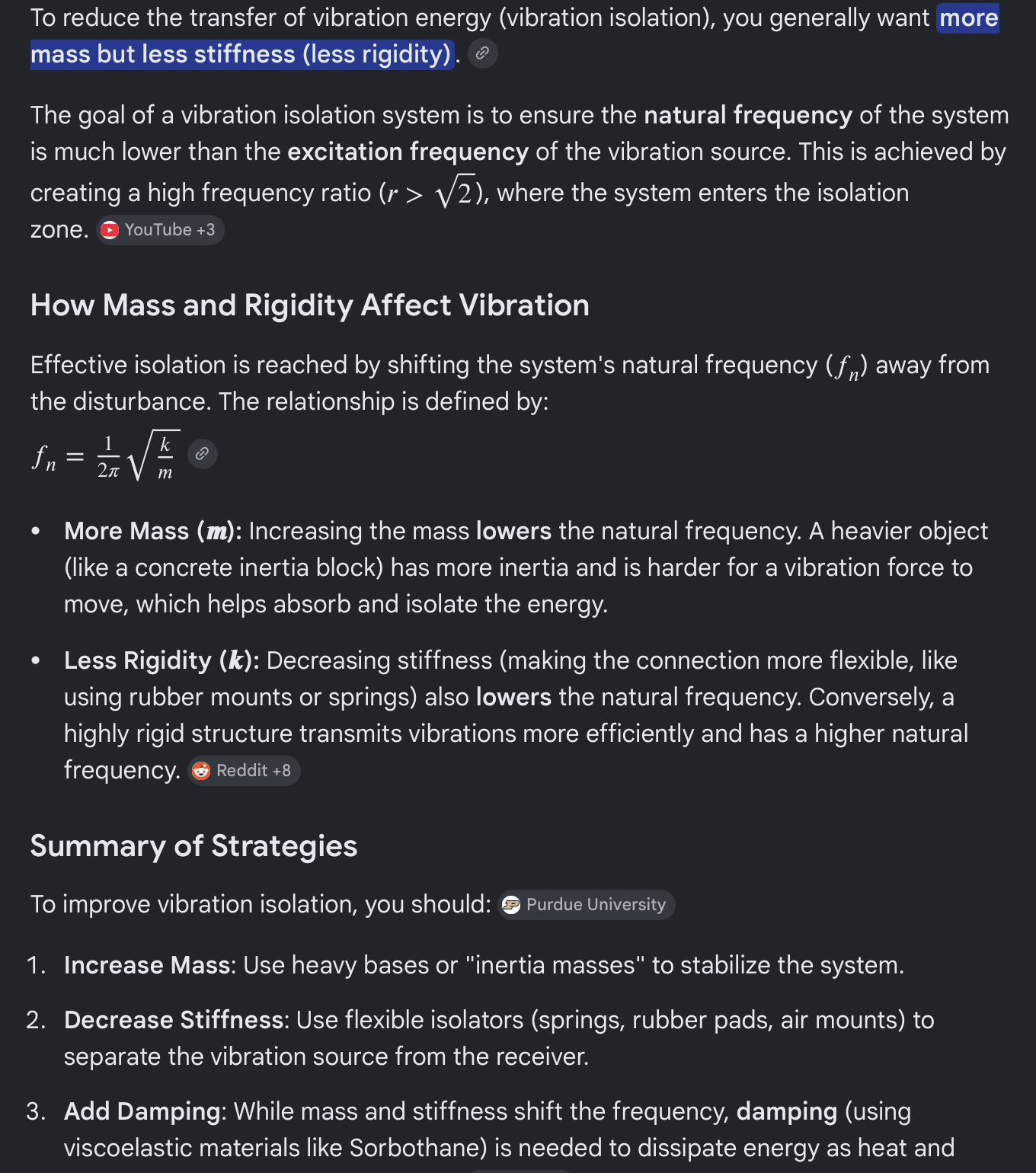
The intuition for stiff mounting is that it keeps the sensor stable relative to the airframe. But that logic breaks down when the airframe itself is vibrating: a stiff connection transmits vibration energy directly into the sensor. The natural frequency of a mounted system is fn = (1/2π) × √(k/m). You want fn well below the engine’s excitation frequencies — which means lower stiffness k and higher mass m. Soft rubber isolators reduce k; adding mass to the isolated platform reduces fn further.
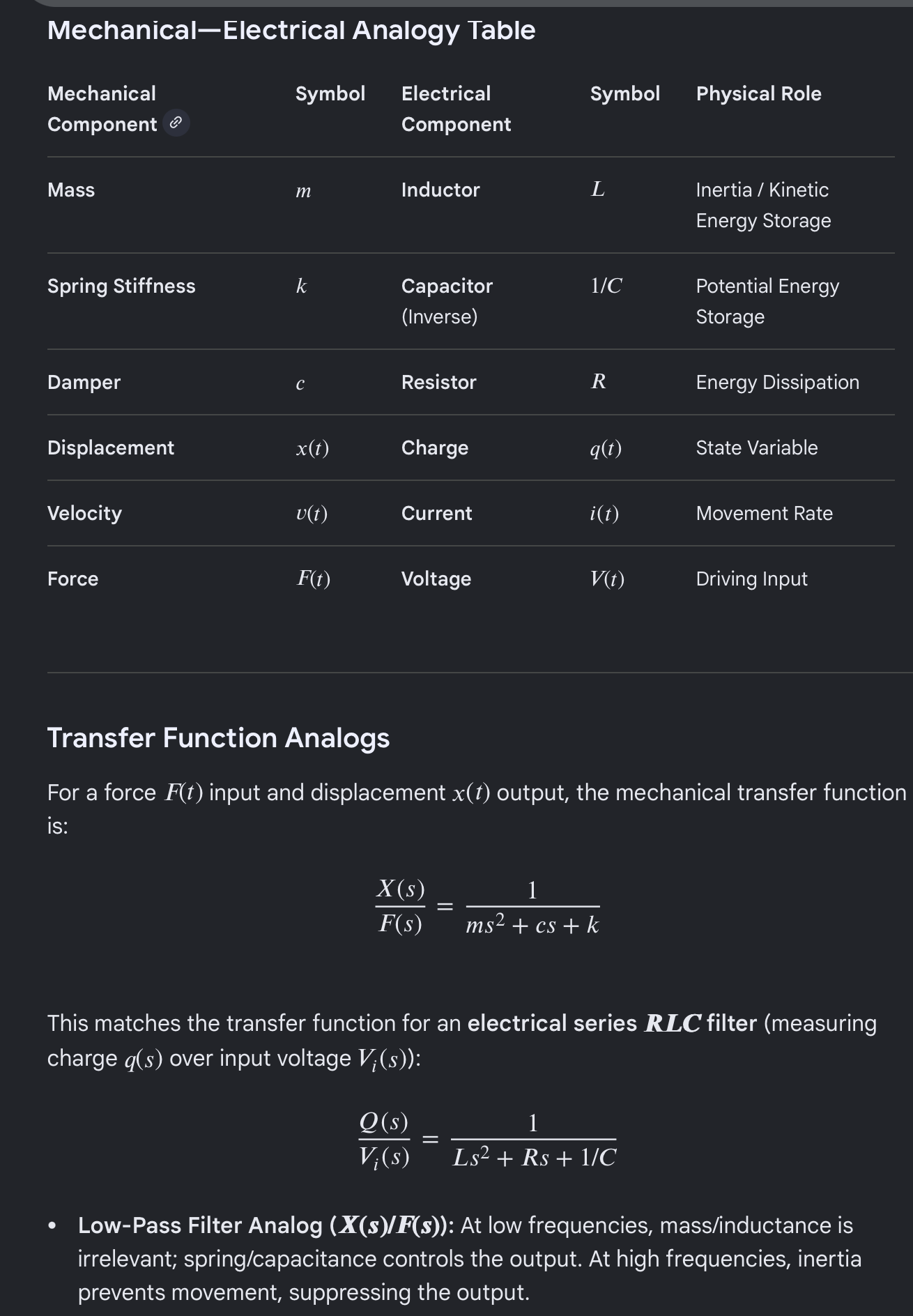
A useful analogy: mechanical vibration systems map directly to RLC electrical circuits — mass to inductance, spring stiffness to 1/capacitance, damping to resistance. A low-pass filter attenuating high-frequency noise is doing the same job as a soft, heavy vibration isolator. The back-of-GDU solution likely works through both added mass and reduced stiffness in the mount path, arriving at isolation inadvertently.
Even Aft Mounts May Need Additional Reinforcement
One builder who relocated to Van’s designated aft ADAHRS mount (behind the baggage compartment) still had significant vibration issues during Phase 1. The eventual solution was adding substantial metal reinforcement to the mount structure. Their full troubleshooting documentation is in a dedicated VAF thread: GSU-25 Remote Mount Vibration Issue — worth reading before deciding on a relocation strategy.
What Garmin Tech Support Confirmed
CAN Bus Dropouts Confirmed in Flights 1–3
Garmin confirmed intermittent CAN bus dropout signatures in the first three flight logs. What causes the 999% hard pegs specifically has not been established — the dropouts are a confirmed concurrent issue, but attributing those particular readings to the bus alone would be premature. Garmin’s guidance: fix the CAN bus first, get clean logs, then evaluate what vibration problems remain.
CAN Bus Length: ~87 Feet vs. 66-Foot Maximum
Garmin’s maximum recommended CAN bus length is 20 meters (66 feet). My estimate puts the total run in N997CZ at ~87 feet — about 21% over spec. Beyond that length, signal reflections and attenuation degrade bus integrity, especially with non-spec cable.
Wrong Wire: Standard Twisted Pair Instead of 120Ω Controlled-Impedance
The CAN bus requires 120Ω characteristic impedance. Standard aircraft twisted pair (~$1/ft) doesn’t reliably hit that spec, causing signal reflections that look like dropouts at the receiver. Garmin specifically recommends Carlisle IT P/N CAN24TST120(CIT) or GigaFlight P/N GF120-24CANB-1 (~$7/ft). Estimated rewire cost: $420–$560 in cable for a 60–80 ft run.
Two Problems, a Ranked Action Plan
Problem 1 — Fix First (per Garmin): CAN Bus. Wrong wire spec, over-length run, confirmed dropouts. Resolve this completely before evaluating what vibration problems remain.
Problem 2 — Address After CAN Bus Is Clean: Vibration. The tumbling horizon and escalating deviation pattern across five flights make it clear something is wrong — the clean-CAN-bus baseline will tell us how much of it is vibration.
- Measure CAN bus run length precisely before ordering wire.
- Rewire CAN bus with Carlisle IT CAN24TST120(CIT) or GigaFlight GF120-24CANB-1. Verify 120Ω termination at both ends.
- Re-fly and pull fresh logs — establish a known-good CAN bus baseline.
- Dynamic prop balance — highest-yield vibration fix, lowest cost. Also explore prop re-clocking.
- Contact Garmin re: SB 2144 — both GSU 25Cs are in the affected serial number range.
- Inspect lower cowl vertical hinge pins for any play. Replace with oversized pins if flex is detectable.
- Evaluate GSU mount options — rubber isolators on current sub-panel location, or relocation to GDU back-panel or aft Van’s mount with reinforcement.
- Post-fix flight test — five clean flights, deviation at baseline, horizon that stays put.
I’m cautiously optimistic that this is all solvable — the VAF community has collectively worked through every one of these failure modes, and there are clear paths forward. But I want to earn that optimism with data, not just a plan.
If you’ve dealt with ADAHRS deviation on your own build, or have experience with the SB 2144 units, I’d love to hear from you in the comments or over on the VAF thread. This community has already saved me multiple trips down dead ends and I’m grateful for every one of those replies.
N997CZ is a homebuilt experimental aircraft (Van’s RV-10). This post documents personal experience during Phase 1 flight testing. Nothing here constitutes maintenance or airworthiness advice. Consult your avionics manufacturer and A&P/IA for guidance specific to your aircraft.
