After the ADAHRS vibration analysis across the first five flights, Garmin’s guidance was unambiguous: fix the CAN bus first, then work the vibration problem. The data showed sustained % deviation throughout every flight — but some of those readings may have been contaminated by CAN bus dropouts rather than pure vibration. You can’t separate the two until the bus is clean.
So before touching the prop balance or the ADAHRS mounts, we pulled the old harness and rewired the entire CAN bus from scratch with the correct 120Ω controlled-impedance spec wire.
Why does this matter? Garmin specifies a maximum CAN bus length of 20 meters (66 feet) using controlled-impedance twisted pair wire. The original N997CZ installation used standard shielded twisted pair — not the specified 120Ω wire — and measured approximately 96.5 feet total. Both the wrong wire and the excessive length can cause impedance mismatches, signal reflections, and the kind of intermittent dropouts Garmin’s tech support confirmed in Flights 1–3.
Before and After: Every Node on the Bus
The CAN bus in N997CZ runs as a daisy chain from the PFD1 terminator through thirteen avionics boxes to the roll servo terminator at the far end. The measurements below are the wire lengths between adjacent nodes — not the lengths attributable to any single box.
Node
Was
New length
PFD1
TERM
│ │
63"
28"
G5
Sockets
│ │
55"
20"
ADAHRS #1
Sockets
│ │
34"
15"
ADAHRS #2
Sockets
│ │
83"
20"
EIS
Sockets
│ │
89"
28"
Audio panel
3-row pin
│ │
86"
28"
GMC507 autopilot
3-row pin
│ │
84"
28"
GAD27
Sockets
│ │
71"
37"
MFD
Sockets
│ │
73"
36"
PFD2
Sockets
│ │
75"
35"
COM2 (GTR20)
Sockets
│ │
32"
28"
GAD29 ARINC
Sockets
│ │
193"
181"
Pitch servo
│ │
220"
208"
Roll servo
TERM
Total
1,158" / 96.5 ft
692" / 57.7 ft
Wire lengths in inches between adjacent CAN bus nodes. New length = larger of wire-only vs. shield & pin measurement. Garmin max: 792" / 66 ft.
96.5 ft
Old total
57.7 ft
New total
−38.8 ft
Saved
66 ft
Garmin max
The new harness comes in at 57.7 ft — comfortably under Garmin’s 66 ft maximum. The old harness was 30.5 ft over spec.
What’s Next
With the CAN bus now on spec wire and properly sized, the next flights will establish a clean baseline. If the % deviation drops significantly, that confirms the old wiring was a major contributor. Whatever remains after that points squarely at vibration — and the prop balance, SB 2144 GSU assessment, and mount evaluation are queued up to address it.
If Flight #3 was the calm, confidence-building morning session, Flight #4 — same afternoon — reminded me that experimental test flying keeps you humble. We got up, noticed something electrical wasn’t quite right, came back down, pulled the cowl, and figured it out. That’s the program, and the Garmin G3X makes this kind of detective work so much easier.
I’m sharing the full data and photos below in case anyone else has been down this road with their IO-540 alternator installation — and I’d genuinely love to hear your thoughts in the comments.
The Setup: Two Flights in One Day
Flight #3 happened early that same morning at KHEF — a roughly two-hour session that went really well. First flap deployments, west-side practice area, calm winds. You can watch the Flight 3 footage here, which covers that morning session right before this one:
By evening I was back at the airport for a second bite at the apple. The controller on duty hadn’t seen our experimental test program before, so we had a good chat on the radio about the practice area setup. During the run-up I noticed the mag drop on each side — left conventional magneto and right SDS CPI-2 electronic ignition — was running around 160 RPM per side, a bit more than I’m used to from my RV-7 background.
Mag drop of ~160 RPM per side with a conventional mag on the left and SDS CPI-2 on the right on an IO-540. Does that sound about right for this combination? I’d really appreciate a comparison point from other builders running this setup.
The Takeoff Smell — and the First Clue
Takeoff on 16L was otherwise normal. Almost immediately after rotation I caught a mild burning smell — subtle, but on a 4th-flight experimental you don’t ignore subtle. I knew we had a small burn spot on the cowl interior from an earlier exhaust pipe contact (now protected with aluminum foil tape and the pipe repositioned), so it might have been residual. But then the electrical picture started to change.
Normally Alternator 1 carries the bulk of the load and Alternator 2 handles residual backup loads. On this flight, Alt 1’s ammeter dropped into single digits — well below what the aircraft was actually drawing. Battery 1 was starting to discharge. Cycling the ALT 1 switch would briefly coax it back, but it wouldn’t hold normal output.
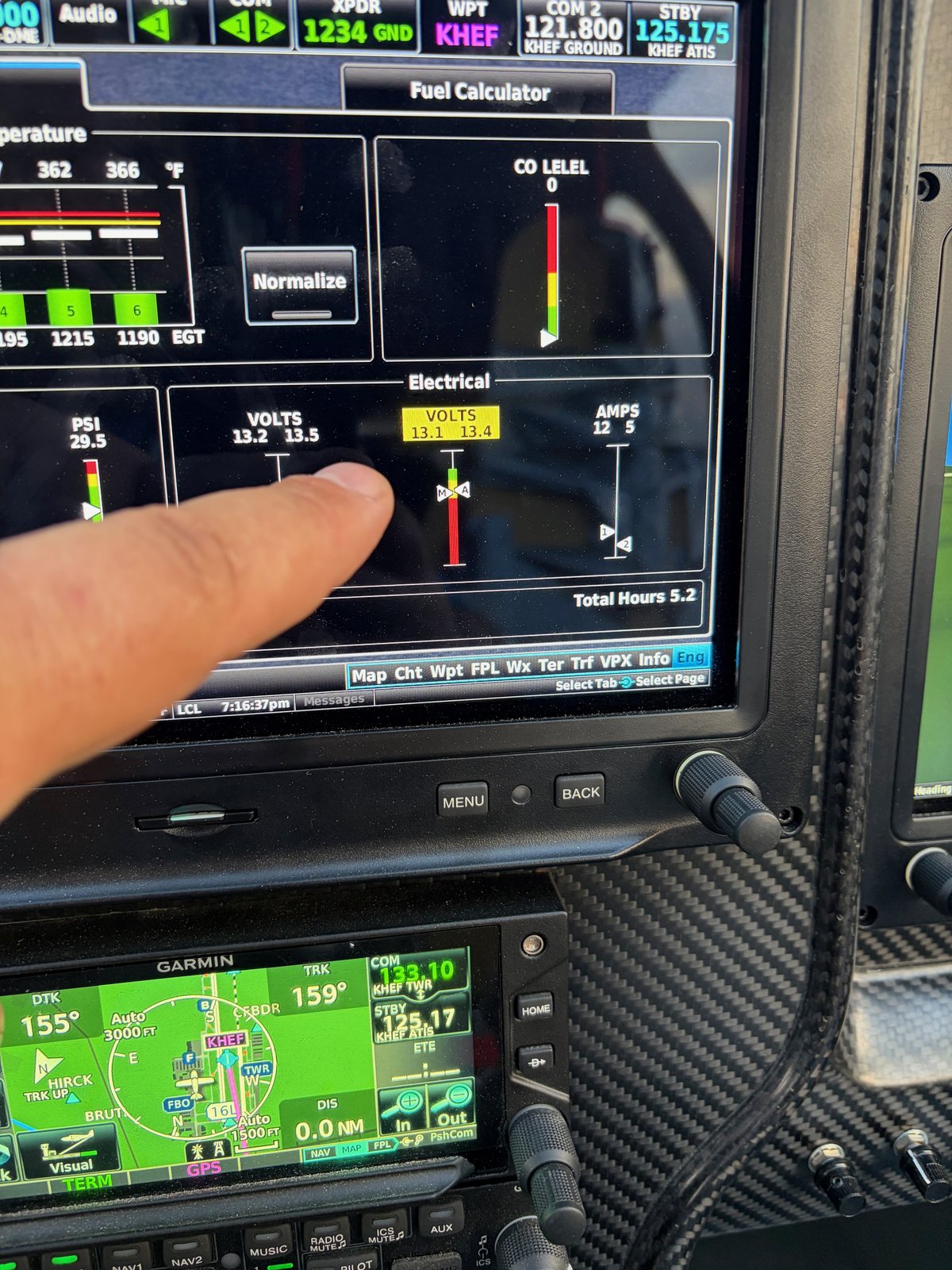
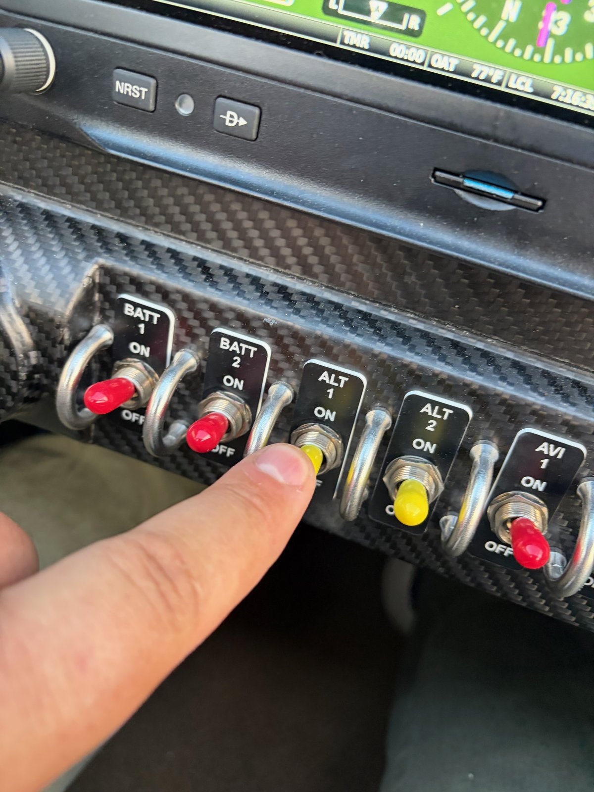
The G3X electrical page showing Bus 1 VOLTS flagged in yellow-orange, dropping out of the normal charging range. Bus 2 stayed healthy throughout. The data log shows Amps 1 fading from ~27A at rotation to just 4–5A mid-flight — well below what the ship was drawing.The ALT 1 switch on the lower console. I cycled this several times in flight — it would briefly recover then fall off again. That intermittent behavior pointed toward mechanical (belt slipping) rather than electrical (regulator or field) as the cause.
What the G3X Data Shows
This was a short flight — about 13 minutes airborne, max altitude 2,031 ft MSL, max IAS 166 kts. But the electrical log tells the story clearly. Bus 2 held solid at 14.1–14.2V throughout; Bus 1 steadily lost ground as Amps 1 faded from 28A to just 4–5A while Battery 1 discharged.
Time
Bus 1 Volts
Bus 2 Volts
Amps 1
Amps 2
Alt (ft)
19:00
13.5
13.9
28
25
298
19:01
13.5
14.0
24
21
1,138
19:02
13.4
14.1
22
16
1,629
19:04
13.2
14.2
13
10
1,722
19:06
13.0
14.2
5
9
2,009
19:08
12.9
14.2
4
9
1,936
19:10
12.9
14.2
4
9
1,083
The decision to return was easy: no imminent emergency — Battery 2 and Alt 2 were healthy, and Battery 1 still had reserve — but continuing to discharge an unknown cause wasn’t prudent at this stage of testing.
Engine Temps: CHTs and Oil Temperature
While the electrical issue was the main story, I was watching engine temps closely too. CHTs peaked at 441°F on CHT-1 this flight, with cylinders 1, 2, 5, and 6 still running warmer than 3 and 4 — a consistent pattern since Flight #1 that seems to be gradually improving with each flight. Cylinders 3 and 4 are now comfortably below 350°F in cruise, which is encouraging.
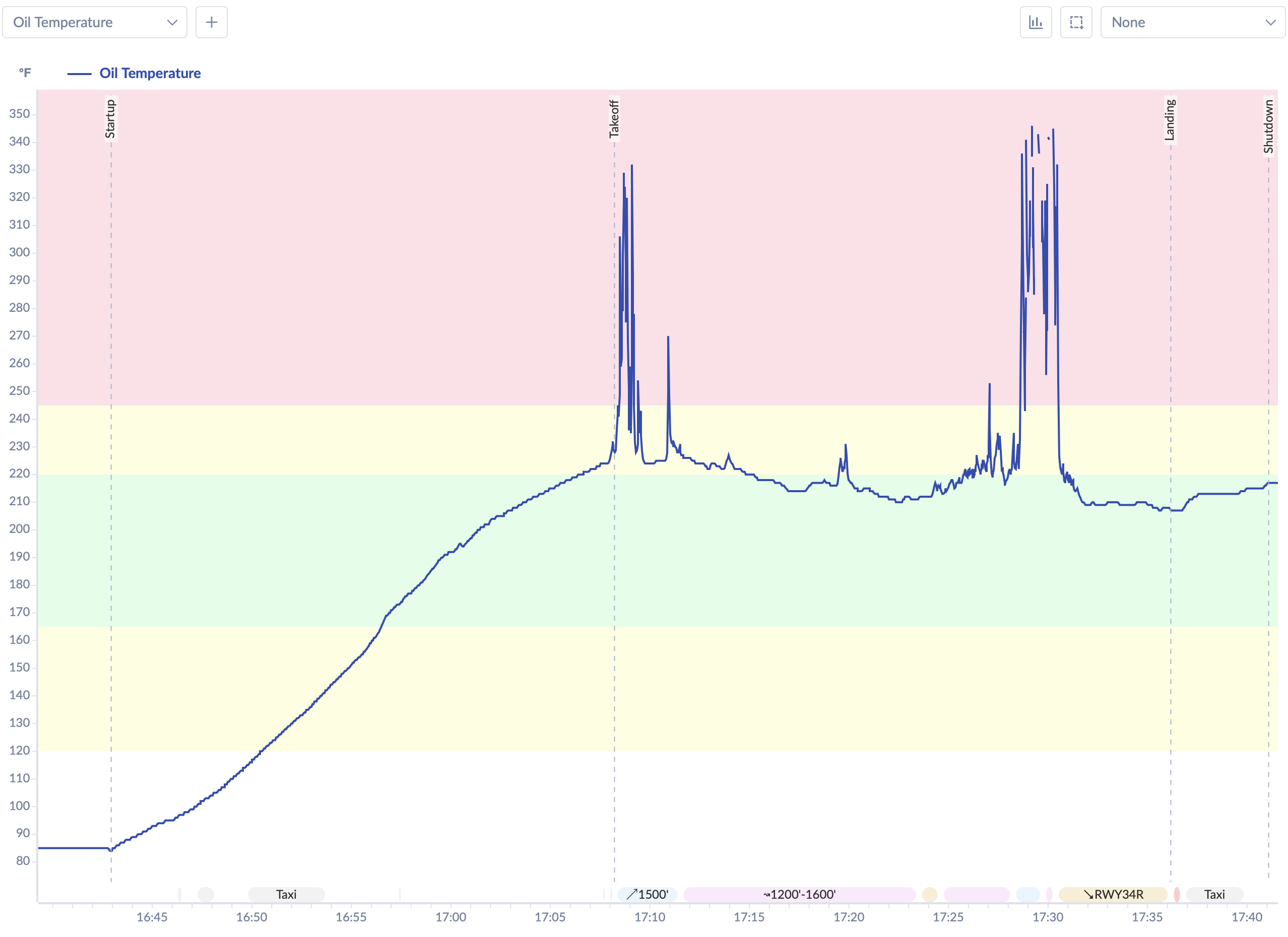
Oil temperature came in at 215–220°F at taxi-in after landing — higher than I’d like, though this was after a high-power takeoff and immediate return to land with very little cruise cooling. We also found the oil cooler airflow door wasn’t quite at 90° open (the winter-operation door should be fully open in summer), so we straightened it. We’ll see if that makes a difference on the next flight.
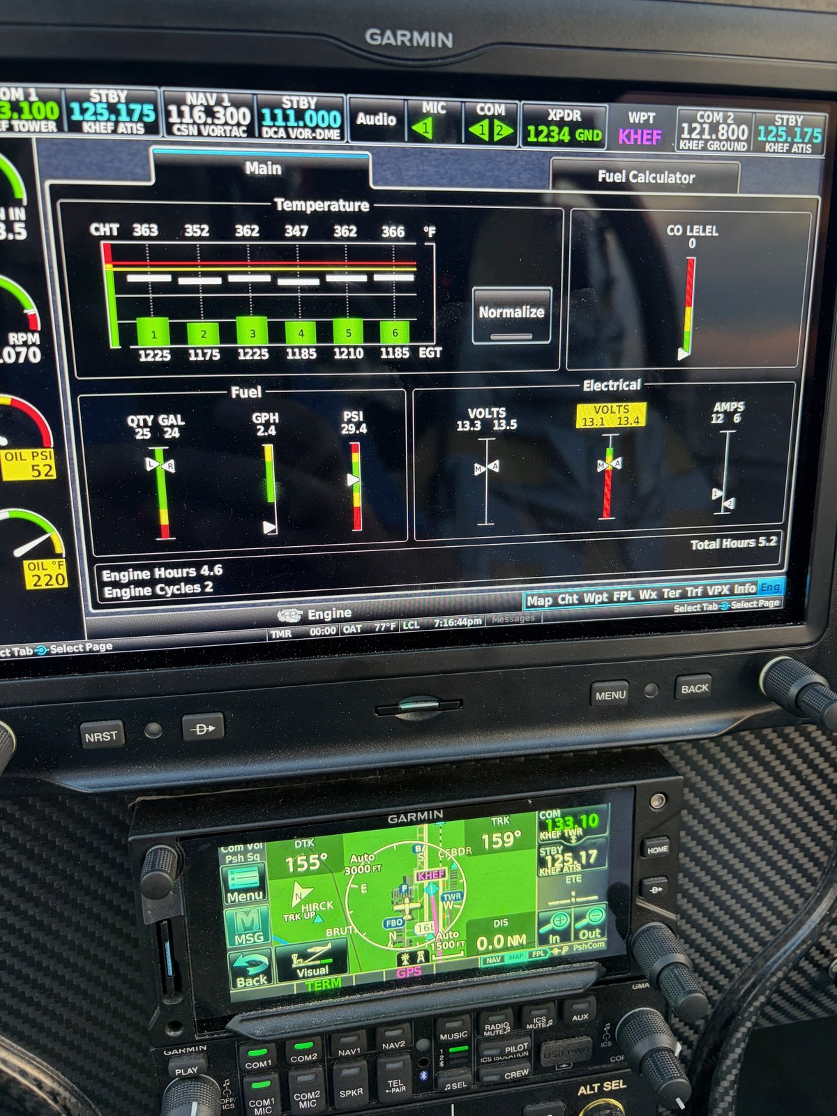
The G3X main engine page mid-flight. CHTs running 363–368°F here, peaking at 441°F on CHT-1 during the flight. Oil temp visible on the left PFD engine section, climbing toward the 220°F seen at taxi-in (OAT 77°F). The VOLTS tile in the lower right is already flagged. Engine Hours 4.6 / Cycles 2.
The Post-Landing Find: Alternator Belt
After landing we pulled the cowl. The culprit was immediately apparent: noticeable slack in the alternator belt. Not a broken belt, not a failed regulator — just insufficient tension. Both the main lower pivot bolt and the smaller tensioning bolt were intact and the tensioning bolt was still safety-wired, but the belt had clearly stretched or the alternator had shifted slightly.
We loosened both bolts, used a screwdriver to lever proper tension back into the belt, re-tightened everything, and re-safety-wired. The intermittent charging behavior in flight — briefly recovering when I cycled the switch, then dropping off again — makes perfect sense in hindsight: the belt was marginal and slipping under load. I’m relieved it wasn’t a chafed or burned wire. Battery 1 went on the wall charger overnight.
The belt seemed fine at install and through the first three flights. Did it stretch after initial heat cycling? Is there a recommended belt tension spec or a “check after first N hours” item for the Lycoming IO-540 alternator drive I should be following? Would love to hear from anyone who’s been down this road.
Oil Cooler Door — Another Small Fix
As noted above, we found the oil cooler winter-operation door sitting at slightly less than 90° open, potentially restricting airflow to the cooler across all previous flights. We adjusted it to fully open. With the shorter flight profile and high-power takeoff, the 220°F oil temp is plausibly explained by the flight itself rather than restricted airflow — but the door is now confirmed fully open and we’ll have cleaner data going forward.
The Landing: A Real Improvement
Not all problems this flight. The full-flap landing at the end of Flight #4 was noticeably better than the steep close-in approach at the end of Flight #3. In Flight #3 I was at virtually full aft stick at roundout with nothing left in reserve — the RV-10’s limited elevator authority at forward CG with full flaps on a steep approach is a real thing.
For Flight #4 I used a much shallower approach angle, carried a touch more power, kept the nose slightly higher, and touched down at about 64–65 knots indicated. The flare felt natural and in-control. This will be the approach profile going forward.
Note on CG: Flying a fairly forward CG for these initial flights — intentional for early test stability — with ballast in the rear seats to nudge it back slightly. Limited elevator authority at forward CG + full flaps + steep approach is a documented RV-10 characteristic. Curious how others have managed approach technique in this configuration during early flights.
Items Still on the List
AHRS 1 tumbling on takeoff: PFD-1’s artificial horizon tumbles consistently when I apply takeoff power — every single flight. PFD-2 stays solid so it’s not a safety issue right now, but I want to understand it. Vibration? Connector seating? Has anyone seen this in a G3X installation?
CHT temperatures: Still watching closely. Peak temps hit 441°F on CHT-1. The hotter cylinders (1, 2, 5, 6) seem to be gradually trending down with each flight as the rings seat. Hoping to see all six under 400°F in level cruise before long — does that sound like a realistic expectation at ~4.5 engine hours, or should I be looking at baffling adjustments?
Fuel float gauges: Still getting hung up at the full position. Not urgent since the totalizer is primary, but the mechanical float/wire fit issue inside the tanks needs to be addressed eventually.
What’s Next
Before Flight #5: re-verify alternator belt tension and confirm Alt 1 charging properly on a ground run. Assuming that checks out, the goal is continued envelope expansion — more time at altitude, more cruise data, and continued CHT monitoring as the engine breaks in.
Your turn: If you have experience with alternator belt tension on Lycoming IO-540 installations, SDS CPI-2 mag drop numbers, G3X AHRS tumbling on takeoff, CHT break-in patterns, RV-10 approach technique with forward CG, or oil cooler management — please drop a comment below. Whether you’re an RV builder, an A&P, or just following along, your input is genuinely welcome here.
Flight 2 took place a week after the first flight, on April 17, 2026. If you haven’t read the first flight post, that’s probably the right place to start — it covers the aircraft, the context, and the CHT spike that set the stage for everything that followed.
This one was shorter, more stressful, and ended with a maintenance discovery that turned out to be both the cause of the problem and a straightforward fix. Here’s what happened.
The Setup
The original plan for Flight 2 was the same as Flight 1: west side of the field, 1,800 feet MSL, north-south legs in the practice area. But when I made the coordination call to Manassas tower that morning, the picture changed.
The controller asked me to keep my pattern on the east side of the field. On the east side, they could give me 1,400 feet MSL — 400 feet lower than Flight 1, and on the side of the field with less room to work in. For a second Phase 1 experimental flight, that wasn’t ideal. But it was what was available that day, so that’s what we did.
Full fuel on both sides — 30 gallons left, 30 gallons right.
The Flight
Takeoff was unremarkable except for two things that repeated from Flight 1: the AHRS-1 attitude indicator tumbled on the takeoff roll (same behavior as before — isolated to PFD1, PFD2 and the G5 standby both remained stable), and CHTs spiked above the warning limits during climb. This time all six cylinders went over 435°F, peaking somewhere in the 460–475°F range before settling down. Higher than Flight 1’s peak, which was unwelcome, and attributable to the later time of day and warmer ambient temperatures.
We were at 1,400 feet MSL with a compact pattern on the east side of the field. Not exactly the relaxed cruise conditions you’d want for watching CHTs settle, but the temperatures did come down as we moved out of the climb and into cruise power.
Then the Oil Temperature Started Misbehaving
Flight 1 had shown clean, stable oil temperature throughout. Flight 2 did not.
Partway through the flight, the oil temperature gauge spiked suddenly to an obviously unrealistic reading — well above what oil temperature can physically reach in a few seconds. I knew it wasn’t a real temperature (temperature can’t rise that fast), but an erratic gauge is still an erratic gauge. I noted it and kept flying.
It happened again. Then a third time — and this time the gauge didn’t just spike, it went dark. No reading at all for a minute or two.
The oil temperature trace from Flight 2. Three erratic spikes to off-scale high readings, followed by the gauge going completely dark. Oil pressure remained stable throughout — the problem was instrumentation, not the oil system itself.
Oil pressure was steady the entire time — 75–80 psi, never wavering. That was reassuring. A failed oil system shows up in the pressure first; the pressure was fine. But flying with no oil temperature indication, in a tight pattern at 1,400 feet, on a second experimental flight, with CHTs that had already been high — that was enough. I made the call to land early and figure it out on the ground.
Total flight time: approximately 28 minutes. Fuel burned: 9.5 gallons from the left tank (confirmed by both the totalizer and the fuel truck, which put exactly 9.5 gallons back in).
The Diagnosis
Post-flight, we went looking for the cause. It didn’t take long.
In the firewall-forward wiring, near the oil temperature probe, we found a crimp connector that hadn’t grabbed the wire properly. When we unwrapped the bundle and pulled on the wire, it came free by hand — zero resistance. That was the culprit: an intermittent connection that would open under vibration, spike the reading to an implausible value, then reconnect. The third time it disconnected, it stayed disconnected long enough to drop the gauge entirely.
I’d actually noticed some finickiness with these wires before the first flight — wiggling the bundle in the hangar had produced erratic gauge readings on the ground. I wasn’t able to reproduce it consistently enough to isolate the cause before Flight 1, and it didn’t manifest during Flight 1. It clearly manifested during Flight 2.
The fix: re-do the crimp, properly this time. Wrap the bundle back up. Done.
Flight 3 would show whether the fix held.
What I Took Away
Flight 2 was short and more stressful than I’d planned. But the outcome was fine—nothing broke, I made a conservative decision to land when my instrumentation became unreliable, and we found and fixed the actual problem before the next flight. That’s the process working as it should.
A few things I’m carrying forward:
Known issues need abort criteria before departure. If something is behaving oddly on the ground, decide in advance what you’ll do if it shows up in the air. Don’t leave that decision for the moment.
Airspace coordination is worth doing ahead of time—and worth holding firm on. Getting assigned the east side at 1,400 feet added unnecessary pressure to an already-demanding flight. For subsequent flights, I’ve made a point to coordinate specifically for the west side of the field. Until I have full confidence in the aircraft and it’s ready to venture further outside the Class Delta for the remaining flight test program, having the more open, higher-altitude practice area on the west side is genuinely important—not just a preference. I’d encourage any experimental builder doing early Phase 1 testing at a busy Class D airport to have that conversation with the tower in advance, and be clear about what you need and why.
The fuel totalizer appears accurate. Having the refueled quantity match the totalizer reading exactly was a genuinely useful data point—I’m more confident in that system now.
As always, if you’ve been through something similar—erratic instrumentation on an early test flight, a wiring issue that surfaced at an inconvenient time, or a tricky judgment call about when to land—I’d really like to hear about it in the comments. I don’t have all the answers on this airplane yet, and the conversations here have been more useful than I expected.